CHAPTER 01
Cold open — What actually makes the hole?
Imagine standing beside an old wooden derrick. You hear a cable tighten, a heavy tool rise, and a blow travel down into the ground. Lift. Drop. Turn. Repeat.
Now move forward to a modern drilling floor. The well turns out into a long lateral. Screens show torque, weight on bit, differential pressure, and rate of penetration. Somewhere beyond the heel, where nobody can watch directly, a cutting structure is meeting fresh rock.
The equipment looks completely different. The basic question has survived: how do you break the next piece of formation, clear it away, and keep the hole usable?
Welcome to GeoNavigate Industry Chatter. This is the first part of our drill-bit history series. We are following the working end of the drilling system: the iron that pounded, the teeth that rolled, and the diamond that learned to shear.
We will meet Howard Hughes, distinguish the father from the famous son, and find out why the history refuses to fit into a neat procession where every new bit makes the previous one disappear.
CHAPTER 02
The percussion era
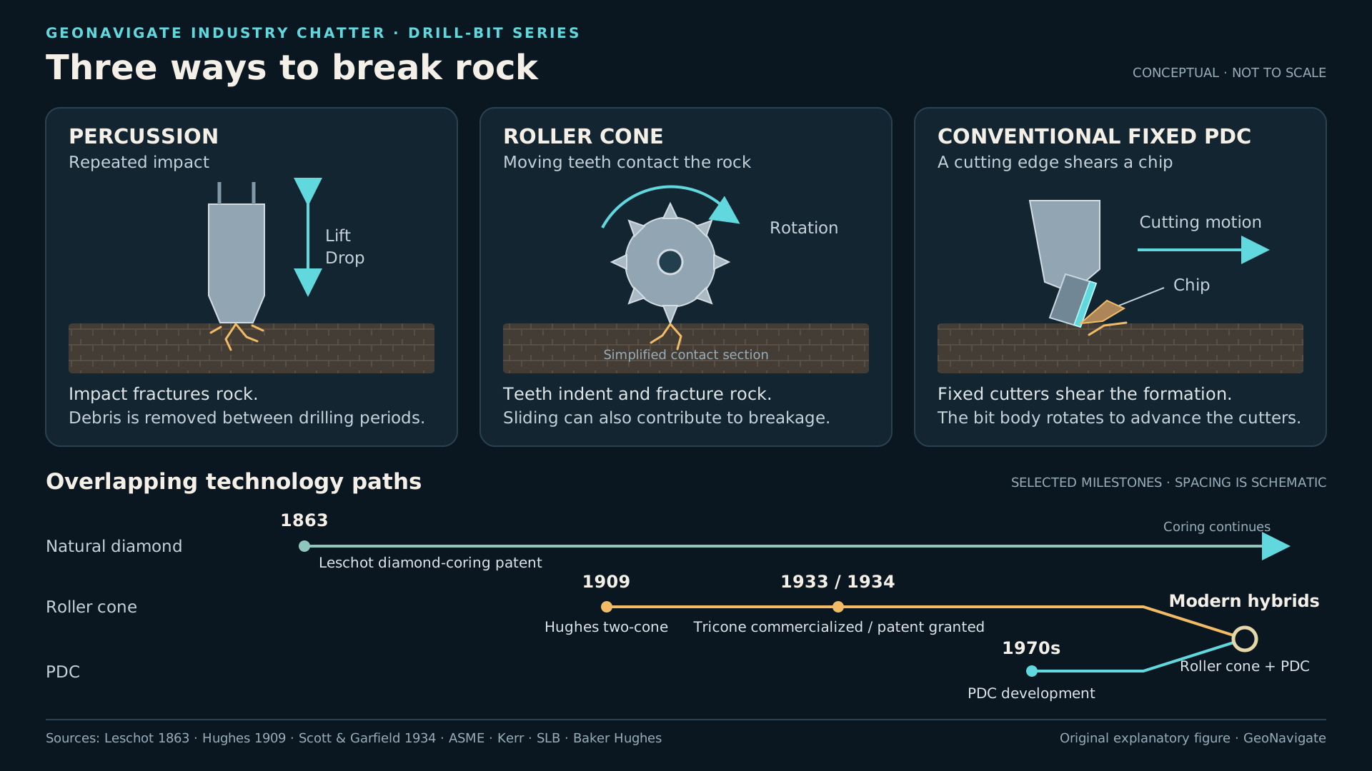
A cable-tool rig breaks formation by repeated impact. A heavy steel bit hangs below the drilling tools. The mechanism lifts it and lets it strike the bottom. A small rotation between blows helps produce a round hole. Drilling pauses for cleaning, and worn cutting edges have to be dressed again. Alberta's historical account describes this rhythm of drilling, bailing, and sharpening.
Picture the bit as the head of a very long, guided hammer. The geology does not care whether the force came from a modern motor or a walking beam. What matters at the contact is the stress delivered to the rock and whether a new fracture can grow.
There is another limit. Broken rock still occupies the hole. If you keep striking through a bed of debris, energy goes into material you have already broken. Making fragments and removing fragments are separate jobs. A useful history of drill bits has to follow both.
Chapter sources1
CHAPTER 03
Spud, spear, arrow: names need a job description
The spudding bit is a documented oilfield tool. A reproduced 1913 Oil Well Supply catalogue distinguishes it from the regular drilling bit and the reamer. The spudding bit opened the larger upper hole; the regular bit deepened it; the reamer restored diameter when needed. Those are different jobs within a drilling system.
Spear and arrow are words that make a strong visual impression. They can describe pointed shapes. But a pointed shape alone cannot tell us what an old tool did. A 1927 patent, for example, calls its invention a spear for oil-well casing or tubing. Its job was recovery: gripping material in the well so it could be pulled out.
That distinction becomes important when a row of old tools is arranged in a museum. The object that looks most like a weapon may belong to the fishing equipment. The broad, blunt object may have been the one that made the hole.
A tool's purpose is more revealing than its silhouette.
CHAPTER 04
Rotary drilling changes the rhythm
Rotary drilling moves the problem from repeated blows toward continuous rotation. The drillstring turns the cutting structure, and circulation can move fluid down through the system and return cuttings toward the surface. During the Turner Valley era, cable-tool and rotary rigs overlapped; Alberta's history describes rotary equipment becoming more prevalent during the 1920s.
That overlap matters. An invention date is not the date every crew changes equipment. People use what they can obtain, repair, power, transport, and operate in the formations they actually face.
Think about a new tool arriving at a remote location. Its advantage on paper is only one part of the decision. The crew also needs the supporting machinery, spare parts, and experience. An improvement at the cutting face can demand changes throughout the operation.
The first lesson in our timeline is practical: technology spreads through working systems, not through dates on a wall.
Chapter sources4
CHAPTER 05
The hard-rock problem and Howard Hughes
Early rotary fishtail bits scraped formation. That worked much better in some conditions than in others. In harder rock, wear and lost diameter could make progress painfully slow. The Hughes two-cone design answered with rotating toothed cutters that chipped and crushed as the bit turned. ASME identifies the 1909 design as a major engineering landmark.
The Howard Hughes in this part of the story is Howard Robard Hughes Senior. The patents name the father. The later aviator and filmmaker was his son, Howard Hughes Junior. The company and the money it generated became central to the son's business empire.
There is a reason the inventor's name belongs in a drilling podcast. A formation that is expensive to penetrate can limit the value of everything beneath it. Changing the cutting mechanism changes what becomes practical to explore.
The story includes a documented design, a hard drilling problem, and the business built around a useful solution. It also reminds us to distinguish an invention from the much larger industry that develops around it.
CHAPTER 06
A moment preserved in a patent
Hughes filed two related applications on November twentieth, nineteen-oh-eight. Both patents were issued on August tenth, nineteen-oh-nine. The familiar two-cone arrangement appears in patent nine hundred thirty thousand, seven hundred fifty-nine. The adjacent patent, ending in seven hundred fifty-eight, describes another arrangement with three cutting members.
Those two documents preserve experimentation, not just a finished legend. The inventor was considering how cutting members could fit inside a strong head, how their bearings could be supported, and how fluid and lubrication could reach the places they were needed.
Imagine turning two toothed rollers against the rock. New edges keep arriving at the contact. The complete bit rotates, while its cutters rotate on their own supports. There are two movements to follow, and both matter.
A sharp tooth is only part of the machine. Something must carry its load. Something must keep its motion possible. An impressive cutting edge becomes useful only when the rest of the tool can deliver it to the rock repeatedly.
CHAPTER 07
Three cones, intermeshing teeth, and the people behind them
The familiar three-cone story has another pair of names. Floyd Scott and Lewis Garfield appear as inventors on the Hughes Tool Company patent filed in April nineteen-thirty-three and issued in December nineteen-thirty-four. Its tooth rows interfit, allowing the cutters to work across the bottom without their teeth colliding. The patent also describes a twisting component of action; a roller cone is not simply a set of perfect wheels rolling without slip.
ASME dates commercial introduction of the Tricone to nineteen-thirty-three. That is why a timeline can legitimately show a commercial milestone in one year and a patent grant in the next.
To picture the movement, first hold the bit body still and turn the individual cones in your mind. Then rotate the whole assembly. Each tooth follows a path through a changing contact.
Watch the coverage. A bit must deal with the centre, the surrounding bottom, and the outer diameter. Leaving a ring or a central pedestal of unbroken formation is a different problem from merely owning a sharp tooth.
CHAPTER 08
Diamond arrives earlier than you might expect
Here is the twist in the chronology. Diamond drilling did not begin after the tricone.
Rodolphe Leschot's United States patent for a diamond rock-boring tool was issued in July eighteen-sixty-three. It describes diamonds mounted around a tubular crown, cutting an annular groove and leaving a central core. Water carries away the debris. That is decades before Hughes's two-cone patents.
Imagine a narrow ring being removed around a cylinder of rock. The centre remains available as a sample. That goal differs from reducing the entire bottom to cuttings.
The distinction is especially useful for a geologist. A bit can be judged by how efficiently it makes a full hole, or by how well it helps recover material that preserves geological relationships. A continuous core and a bag of cuttings answer overlapping questions, but they are not the same evidence.
So imagine the history as several branches: percussion, roller cones, natural-diamond coring, and later synthetic-diamond cutting. Useful ideas can develop alongside one another and meet again in different applications.
Chapter sources10
CHAPTER 09
Synthetic diamond has to become a working bit
A polycrystalline diamond compact, or PDC cutter, combines a diamond cutting layer with a supporting carbide substrate. On a conventional PDC bit, cutters are mounted in the bit's blades and shear rock as the assembly rotates.
A very hard cutting material is promising. But the surrounding engineering decides whether it survives a run.
Callin Joe Kerr's technical history traces PDC development from the nineteen-seventies. Early field testing exposed practical weaknesses: cutter attachment, impact damage, inadequate cutter exposure, and cleaning problems. The history describes improvements in cutter support and brazing as the technology developed. It is evidence of a difficult engineering progression, rather than instant success when synthetic diamond first appeared.
Think of a good knife held in a weak handle. Improving the edge alone does not make the complete tool reliable. The cutter has to remain attached, its support has to survive, and broken rock has to leave the cutting area. Each successful run tests the whole arrangement.
CHAPTER 10
Matrix body and steel body are construction choices
When someone says matrix-body PDC, they are describing the body that supports the cutting structure. They are not naming a separate cutting mechanism that comes after PDC on the timeline.
Steel and tungsten-carbide matrix bodies offer different balances of strength, wear resistance, and design freedom. SLB's technical overview explains why steel supports relatively tall blades and open flow paths, while matrix bodies provide wear resistance but require attention to brittleness and geometry.
That makes a useful question for our next episode: what problem is this particular body intended to solve?
Consider blade shape, the space between blades, and the routes available for fluid and cuttings. A bit that looks solid and impressive on a display stand still has to function at the bottom of a well. The empty spaces are part of its design too.
Chapter sources11
CHAPTER 11
A few degrees can change the cut
Now zoom in from the entire bit to one cutter. Back rake and side rake describe different parts of its orientation. Changing that orientation changes how the cutting face meets the rock.
A published single-cutter study by Rajabov and colleagues tested more than one hundred fifty combinations. It found that rake angles, depth of cut, rock type, and pressure affected cutting energy and aggressiveness. Lower back rake improved cutting efficiency in the reported comparisons, while cutter durability remained a tradeoff. Those results are experiments under stated conditions, not a universal instruction to select one angle for every bit.
Picture the cutter from the side, then from above. Its backward lean and its sideways orientation are different adjustments. A number beside it means little until we know the reference from which that angle was measured.
Now add a second cutter. The design question changes again. Does it meet fresh rock, a ridge left by its neighbour, or material that has already fractured? A complete bit is an arrangement of interacting contacts, not a photograph of one ideal cutter repeated around a circle.
Chapter sources13
CHAPTER 12
Hybrid bits and combined mechanisms
Hybrid bits bring roller-cone and fixed PDC cutting elements into the same design. Baker Hughes describes its Kymera family as combining crushing with shearing, with intended benefits in difficult and interbedded applications. Manufacturer performance claims need their operating context; the existence of both mechanisms is the essential point here.
The story has come full circle. An older mechanism can remain useful inside a newer tool.
The better comparison asks what the formation demands, how the assembly behaves, and what evidence shows that the bit completed the intended interval effectively.
Sometimes the most impressive figure is speed. Sometimes it is a section completed without another trip. Sometimes it is the ability to maintain the planned trajectory while the cutting structure survives changing rock.
Chapter sources14
CHAPTER 13
Closing — The formation gets a vote
Across this history, the same conversations keep returning. How does the rock break? What supports the cutter? Where do the fragments go? What does the tool cost over the interval it actually completes?
For the wellsite geologist, that creates a useful habit. Treat a change in drilling response as evidence that needs context. Put the lithology, cuttings, GR, drilling parameters, and operating changes beside one another before telling the story of what the bit has encountered.
In the next part, we will move inside the modern PDC bit: steel versus matrix, back rake and side rake, blade and cutter geometry, and the difference between a design that cuts aggressively and a system that drills efficiently.
This is GeoNavigate Industry Chatter. From the spudding bit to synthetic diamond, the tool changes. The formation still gets a vote.